To be able to select fins and size them for our rocket, here I present a small guide to estimating the forces on the fins.
A simplified analysis of the forces on the fins can be performed by imagining they are a flat plate at a small angle of attack, cantilevered at the rocket tube. The fins therefore produce some lift, and this can be modelled using plate bending theory, or even more simply a flat plate assumption.
¶ Which forces do fins feel?
A lift force, and a drag force. But the drag force on a thin plate at a small angle of attack is quite small, and the fins need to be designed to take on the root bending moment.
We will calculate this load using a few different methods: A point load assumption and a cantilevered beam model. In the future, we may try to solve this using plate bending theory, or FEA.
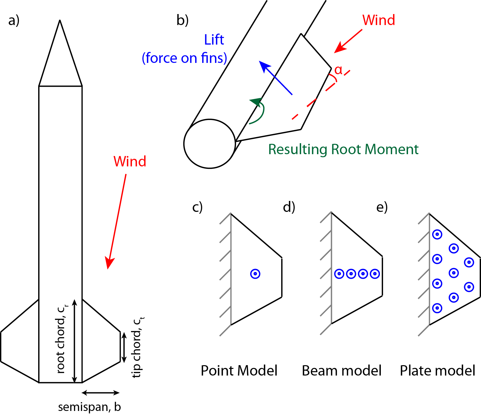
¶ Model 1: Point loads
We can use a very simple approximation to find the order of magnitude of the root bending moment. We assume that this is a flat plate, with some small angle of attack α, and that it feels a single concentrated force at the centre of fin.
¶ Derivation
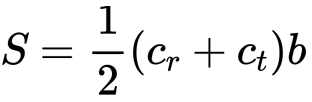
The total area of the fin is simply
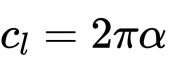
A flat plate has a lift curve slope of 2π, and so we can make a simple approximation of the lift in terms of the angle of attack (in radians):
Therefore, the total wing produces a lift of magnitude,
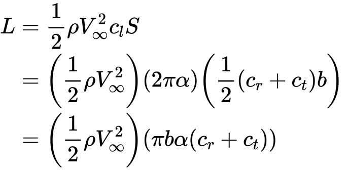
(with α defined in radians)
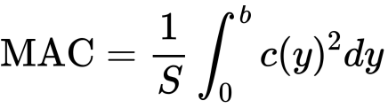
To find the moment arm, we will need to find the mean aerodynamic chord, and then find the y location of that chord.
For a single fin (with geometry defined above), the mean aerodynamic chord is defined as,
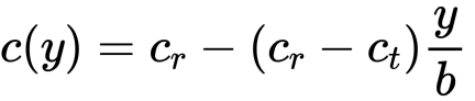
Next, we need to find the chord as a function of the y coordinate:
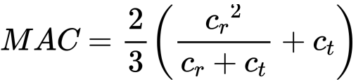
therefore, the MAC of this fin is given by:
Now we can solve for the y location of the MAC, using the previous equation.
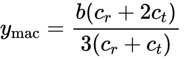
Therefore the total root bending moment is given by
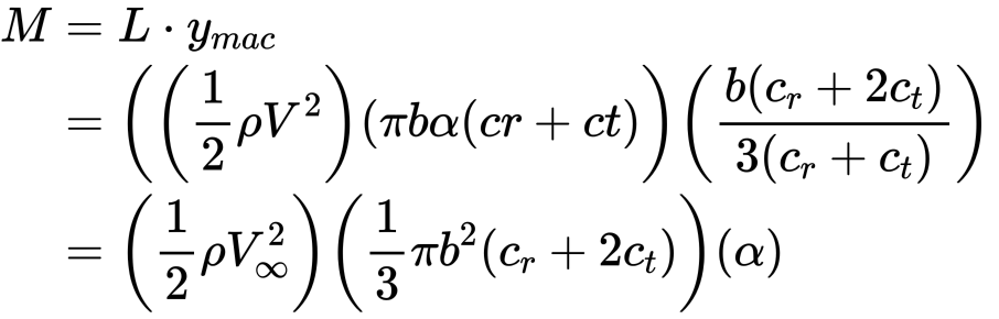
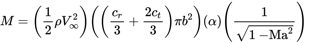
If you want to include the effect of compressibility, you have to include a Prandtl Glauert correction, that is only accurate upto Ma<~0.7)
Note: The classic fuselage correction on lift (1+(total wing span/fuselage diameter)^2) factor may not be relevant to our problem. Using approximate numbers from Sporadic impulse, that factor evaluates to 10. The correction was designed for medium-high aspect ratio aircrafts, not our very low aspect ratio fins.
Therefore, we see that the root bending moment is proportional to
- dynamic pressure
- angle of attack
- the span, squared
- and (cr + 2ct)
- compressibility factor
Therefore, the fins root bending moment is primarily sized by the maxQ condition, but you need to be generous with the angles of attack in case the rocket is hit by a gust at this condition! (See below for gust correction)
¶ Sample Calculation (for a rocket similar to Sporadic Impulse)
Suppose our rocket has the following parameters:
-
Geometry:
- Root Chord: 12 in = 0.3 m
- Tip Chord: 6 in = 0.15 m
- Semi-span: 6 in = 0.15 m
-
Flight Conditions:
- rho=1.225 kg/m3
- max V = 255 m/s
- Ma = 0.77 (slightly outside the PG correction region, but we will use it for now)
Using
We get a bending moment of
M = 882.5 α if α was in radians, or
M = 50,561.6 α if α is in degrees
which means that (note this isn't an accurate table)
| alpha (deg) | Bending moment (kN m) |
|---|---|
| 0.1 | 5.06 |
| 0.5 | 25.3 |
| 1.0 | 50.6 |
| 5.0 | 252.8 |
These are definitely not insignificant, but luckily, if our static margin is large enough, our angles of attack should be very small for most of our journey.
In fact we can see what this is like, on a representative openRocket Simulation (Sporadic Impulse, 5 Dec 2019)
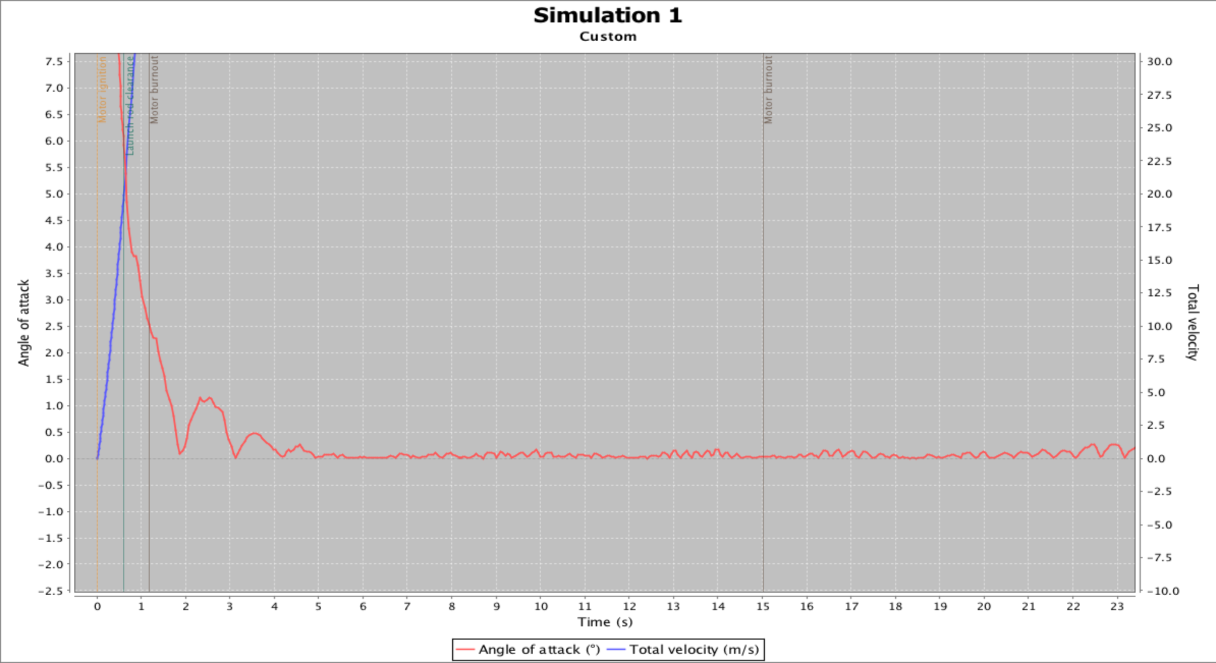
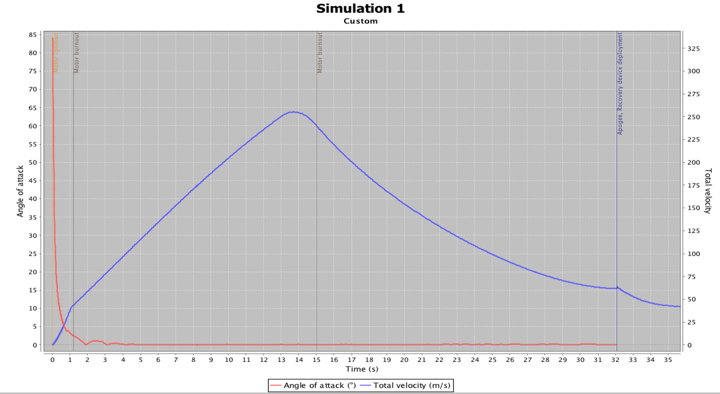
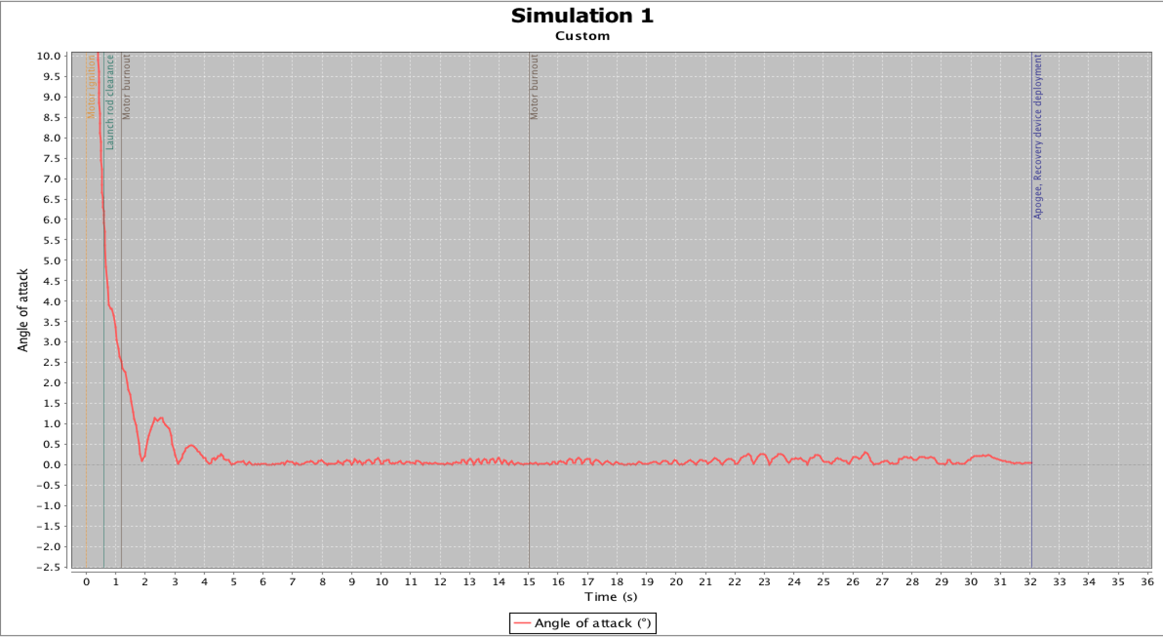
Notice that after the launch rod clearance, the angle of attack is always less than 5 deg, and gets to be less than 0.5 from about 3 seconds into flight.
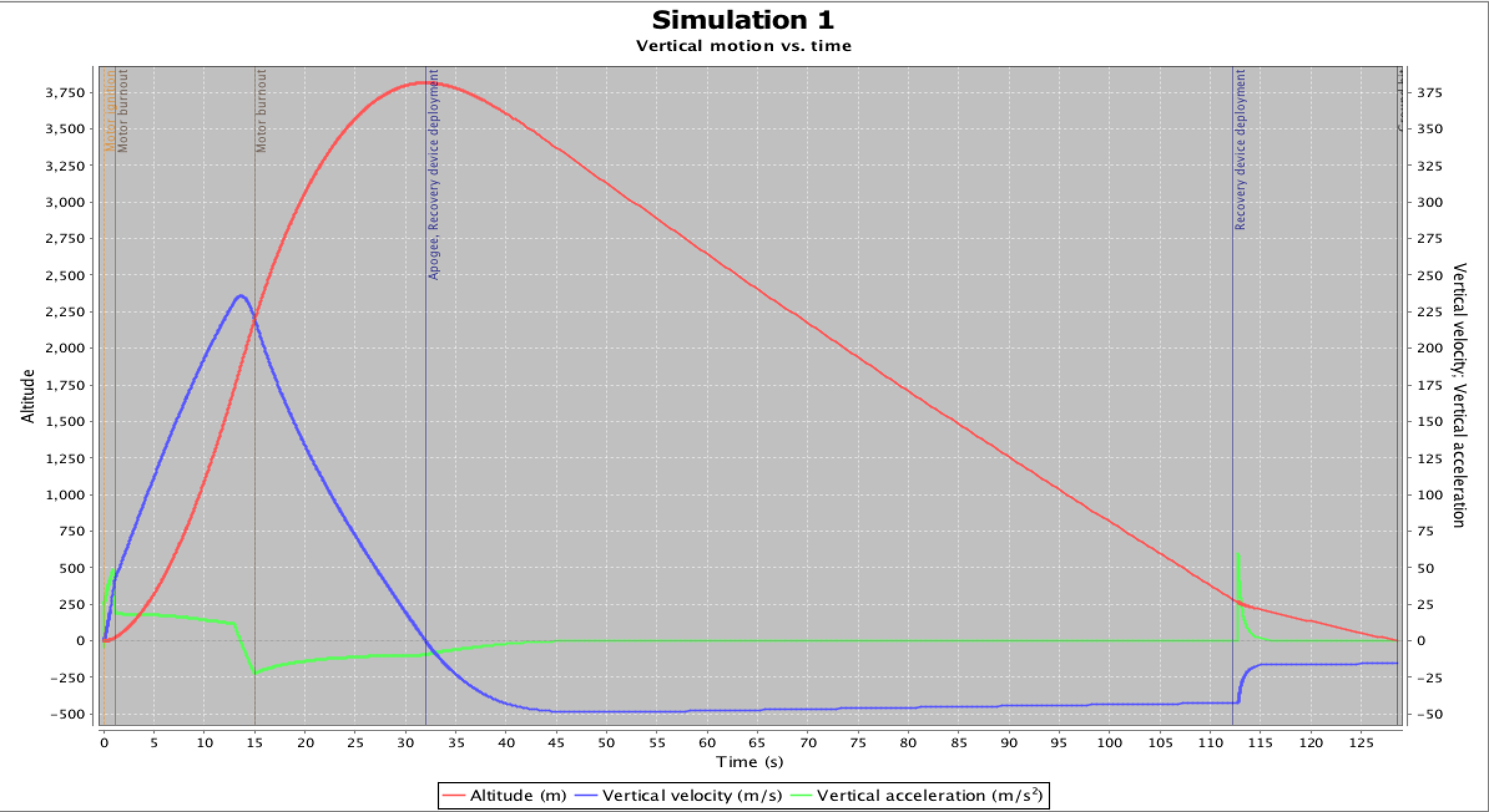
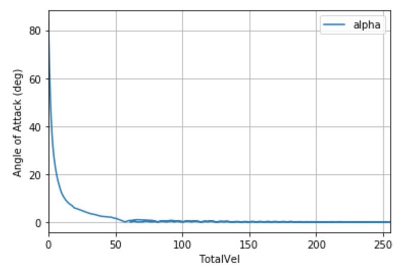
Some more useful plots are:
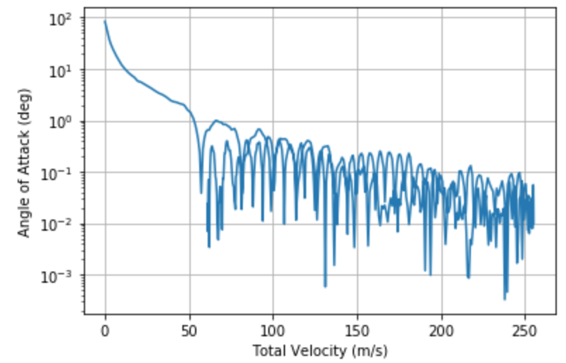
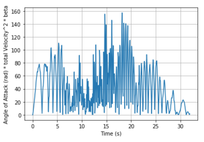
Using the last plot where we club together the effect of , we can say that (alpha (rad) * V^2/sqrt(1-Ma^2)) will stay below 160 rad m^2/s^2 for this rocket.
Therefore if we still assume rho=1.225 kg/m3 throughout, we can get the following estimate on the total bending moment of the rocket:
| Condition | Bending Moment (N m)(THIS IS WRONG SEE BELOW) |
|---|---|
| Bounding Case | 1.385 |
Which is really small! Note, this simulation was done with wind speeds of about 2 m/s, but really should be done with wind speeds on order of 30 m/s for worst case analysis
However this isn't what sizes the fins!! You have to worry about gusts!
To deal with gusts, we need an estimate on what the gust can look like. There is a very good explanation of this (and currently being implemented in full in rocketPy) from AspireSpace: http://www.aspirespace.org.uk/downloads/Rocket%20vehicle%20loads%20and%20airframe%20design.pdf
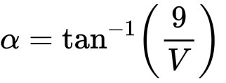
For fins, the most important point is that the gust can be modelled as a 9m/s step increase in horizontal speed. That implies that there is suddenly an increase in alpha. Let's estimate this increase in alpha.
As an approximation, we can assume the rocket is going straight up (as we say earlier the $\alpha$ goes to 0 very quickly) and is flying at a speed V. Then it sees a 9 m/s wind gust, and therefore the alpha is
| V (m/s) | alpha (deg) |
|---|---|
| 30 | 16.7 |
| 50 | 10.2 |
| 100 | 5.1 |
| 250 | 2.1 |
Which ends up changing the graphs to look like these:
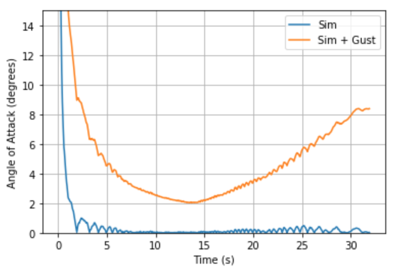
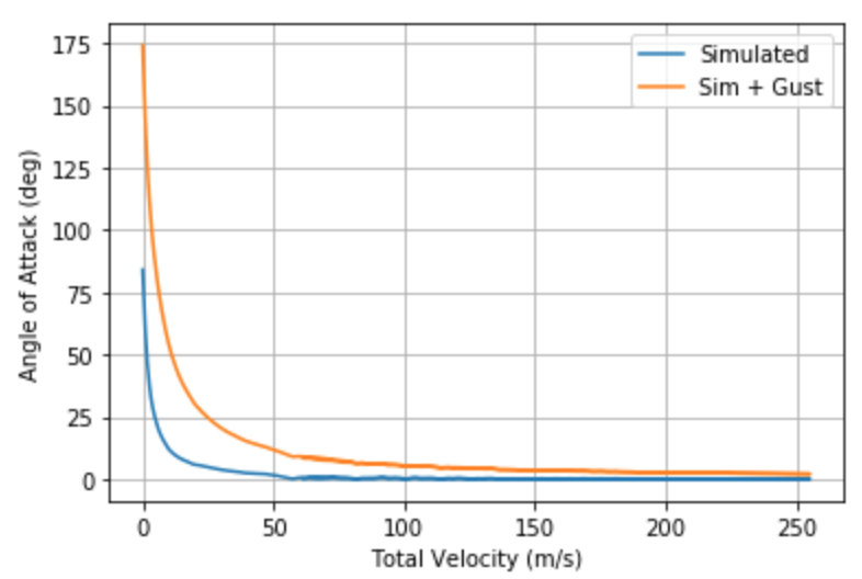
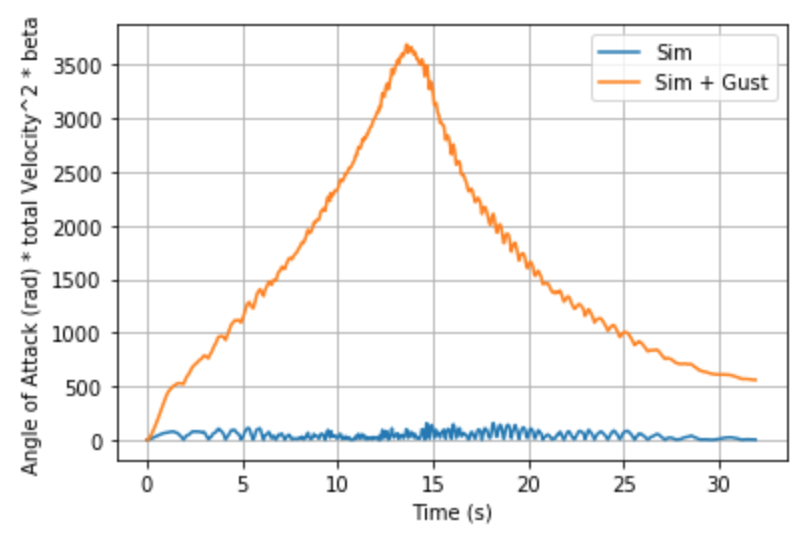
Which is definitely far greater than anything we've designed for at the moment!
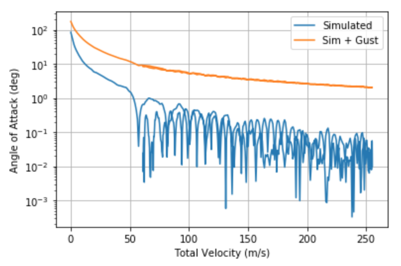
And the most important graph:
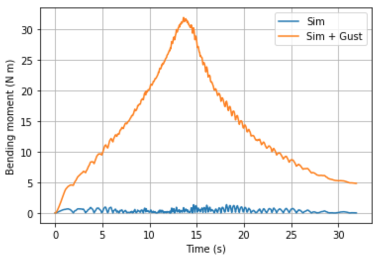
So overall, it seems we need to design our fins to sustain about 35 Nm of root bending moment.
This is equivalent to placing about 24 kg of load at the tip of any single fin!
Method 2: