¶ Separation Systems Without Blackpowder. 2021
¶ Context
The ejection of a parachute is critical for recovery of a rocket. This is typically achieved using an ejection charge. Due to the difficulties of obtaining an ejection charge in the United Kingdom as a result of more strict laws involving the handling of explosives as compared to the United States. Here, a series of different approaches are outlined, which attempt to separate a rocket without blackpowder. This is including but not limited to mechanical processes or carbon dioxide ejection systems. For 2021, Roy, Ishaan , Ting, Jayden and Schiavo, Vincenzo are looking into and conducting research in this field.
¶ Brainstorming (20/03/2021)
The first stage in our design process was brainstorming. Here, we suggested many ideas, neither were very heavily developed, with just simple explanations of their processes outlined below.
- Distribution of CO2 within the body: improved diaphragm system to channel the flow into certain high pressure points.
Context: It may result in a lot of wasted pressure and thus energy if the CO2 canister expands within the main parachute bay. Even though there are about 6.895 bar of pressure inside a CO2 canister and only about 0.5 to 1 bar of pressure is sufficient to separate a small rocket, we felt that for a sufficiently large rocket it is best if all of the pressure is distributed as efficiently as possible.
Concerns: Our main concern were (1) the volume might be too large, (2) no space for the parachute to slot into if it was cordoned off, (3) the pressure distributed against the sides of the walls i.e. normal to the sides is mostly wasted and increases the frictional forces in the fit and (4) if a system is created how does one prevent the system from leaking.
V1 : The solution to these issues was developed once and then further developed to meet certain characteristics. In V1 , the design was simply a smaller confined area, with channels that could redirect the force to the outer edges where the friction fit was located, this would mean that the pressure would be maximised at the edges and would be focused. A drawing of V1 is outlined below. The high pressure reservoir (the mechanisms by which this was created are exempted here, it assumes that there is a valve connected to a power source) opens up into the chamber and the CO2 flows to the edges, due to it being connected as a separate entity to the main body tube, no pressure is directed to make the friction fit stronger.
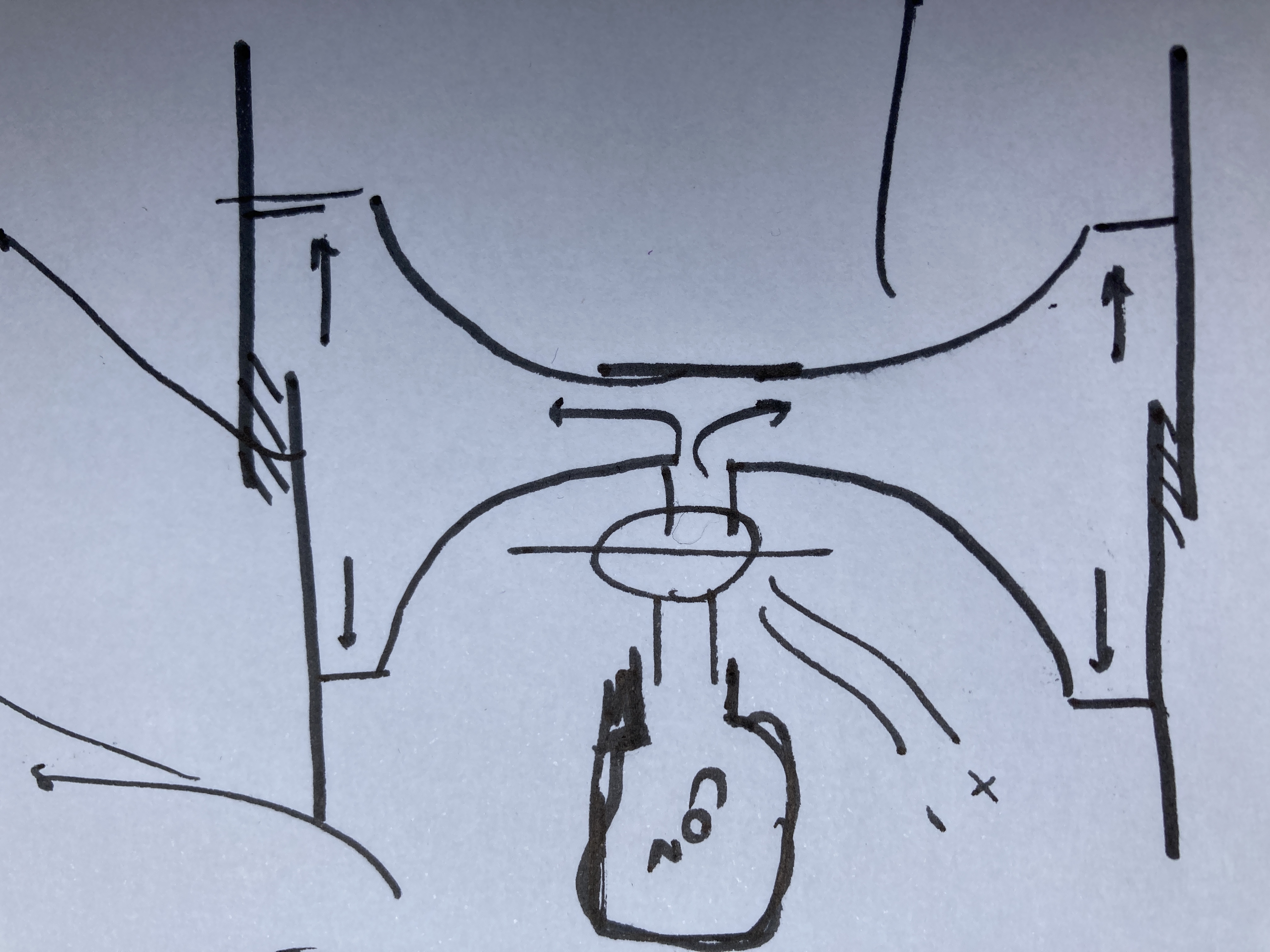
V2 : There was however, a slight issue with V1 in the fact that though it addressed concerns (1) and (4), it still distributed pressure onto the side walls, which rendered it somewhat redundant for issues (2) and (3). To solve issue (3) it was made such that it was separated from the side walls, as in being a separate entity entirely, thus there can be a controllable friction fit in between which is only there as a placeholder really. Moreover, this means that the pressure is not distributed onto the side walls. To address issue (2), the design was turned into a torus, so that it had an exposed inner section that then allowed a parachute to slot into.
- Puncture of CO2 canisters
The below designs all outline various ideas in which a CO2 canister is punctured and then this released the CO2. When the CO2 canister is punctured it would then flow into the above designs probably V2 , and this would then separate the system. This is the traditionally accepted mechanism for CO2 release.
- Linear Actuator*
General: A linear actuator is probably the most simple and reliable of methods to puncture a CO2 canister. As can be inferred, it involves a linear actuator with a spike attached to it. Said spike would be needle like in dimension. It would be propelled into the CO2 canister at the top, being held in place, by some sort of fixed sleeve. The needle would then be either (1) pushed back by the force produced by the high speed CO2 flow or (2) be retracted by some form of electronics, reversing the current output.
How: A CO2 canister is designed to be punctured this means that the metal on the upper surface is sufficiently thin, so as to allow for a sharp tip to enter through the top. By retracted, or being propelled out, this prevents extreme choking of the flow, and allows the pressure to fill the pressurisation chamber sufficiently fast so as to cause separation.
Advantages: (1) It is a simple and reliable design, which is likely to be able to punch a hole in the top of the canister, allowing the CO2 to flow out very easily. (2) It doesn't require significant design aside from designing a sleeve to hold the CO2 canister in and a special pin to punch into the canister to allow the CO2 to flow through and not obstruct or choke flow. (3) It is self contained and may easily be expanded to cater for more CO2 canisters provided the need arises, with the simple change of changing the pin. (4) The electronics are quite simple involving the application of current and then the deactivation (if it is self ejecting) or reversal (if it chokes the flow).
Disadvantages: (1) It may be very expensive, because from prior research, the prices of linear actuators are generally in the price range of £50, for sufficient force to be provided. (2) For the size of linear actuator required the mass might increase significantly, which will impact the rocket characteristics. (3) Due to the lack of significant testing and research into the exact force required to puncture a CO2 canister, some research and testing must be conducted to determine the exact force. (4) The design for the pin, will be very complicated, complicating as well as increasing the cost of manufacture.
- Electromagnetic Varieties: These are a series of slightly more complicated mechanisms of piercing which involve the usage of a sharp pin to pierce them, They aim to create simplicity in the fact that the pin is unattached to a rigid arm, this means that when it pierces into the CO2 canister, it is automatically a given to be self ejecting. This is almost analogous to the CO2 Raptor design by Tinder Rocketry. However, it replaces the explosive charge with electromagnetic repulsion.
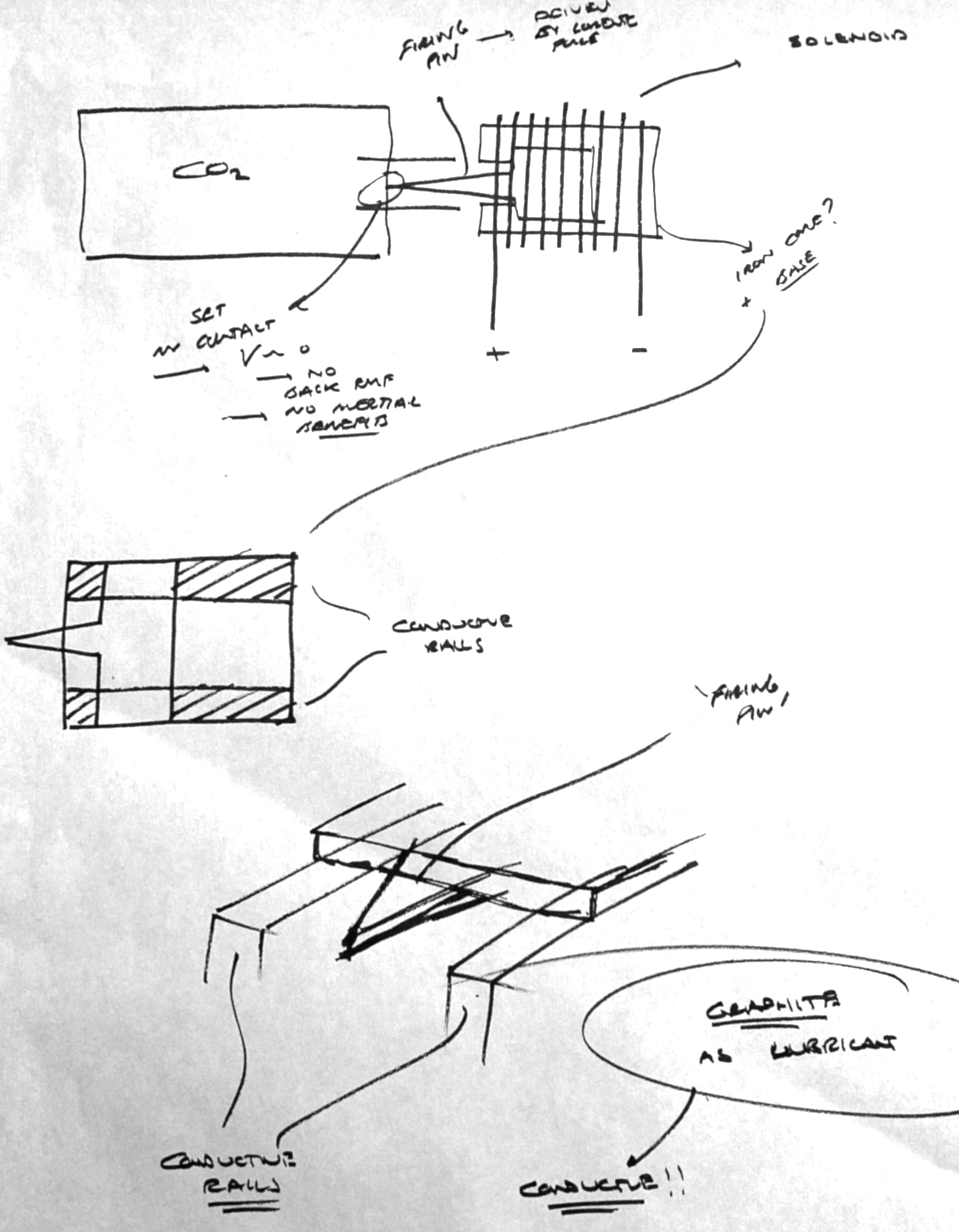
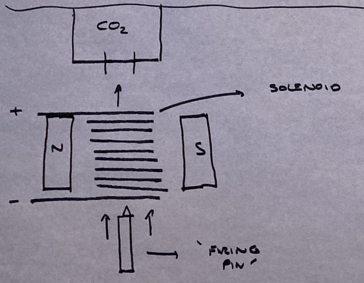
- Firing Pin through Solenoid.
General: This method intends on puncturing the CO2 canister, it tries to improve from designs with a linear actuator by having an unconnected 'firing pin', which can puncture the CO2 canister, and falls away into another part of the rocket, but doesn't obstruct the flow of the CO2 canister.
How: The firing pin, moves upwards, and is accelerated by the magnetised solenoid, increasing the velocity up to the point that it can puncture the CO2 canister. The entrance into the solenoid is used as the trigger when the system is activated.
Advantages: (1) There is no chance of choking the CO2 flow, because the pin is removed. This means that the maximum force and pressure can be released. (2) Given the cylindrical design this means that it could all be perhaps simplified into the form of a cap that wraps on to of the CO2 canister, allowing usability in other rocket designs. (3) The current only needs to be activated in one direction and for a short transient time because the pressure released will be sufficient to propel the pin far away.
Disadvantages: (1) IT WOULD NOT WORK BECAUSE A THEORY KNOWN AS LENZ'S LAW IN WHICH, WHEN SOMETHING ENTERS AN ELECTROMAGNETIC AREA, LIKE SO, EDDY CURRENTS ARE FORMED INSIDE AND BY THE CONSERVATION OF ENERGY, ALL OF THE MOTION IS TAKEN AWAY. THIS IS THE PHENOMENON WITH WHICH CARNIVAL RIDES OPERATE. (2) Also the pin, may tumble around and cause damage to other areas in the rocket.
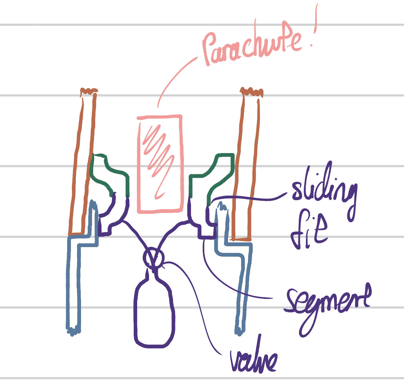
- Rails.
General: Instead of passing a pin through a solenoid, the electromagnetic serves instead as a purely repulsive force, which repels a 'firing pin' attached to some rails, it then slides into the top of the CO2 canister. This ensures that the pin isn't lost within the rocket body tube, thus causing no damage to sensitive areas like electronics. Moreover, it also furthers on the concepts and abilities of the through solenoid idea, in being basically freely attached, it doesn't choke or block flow in any way.
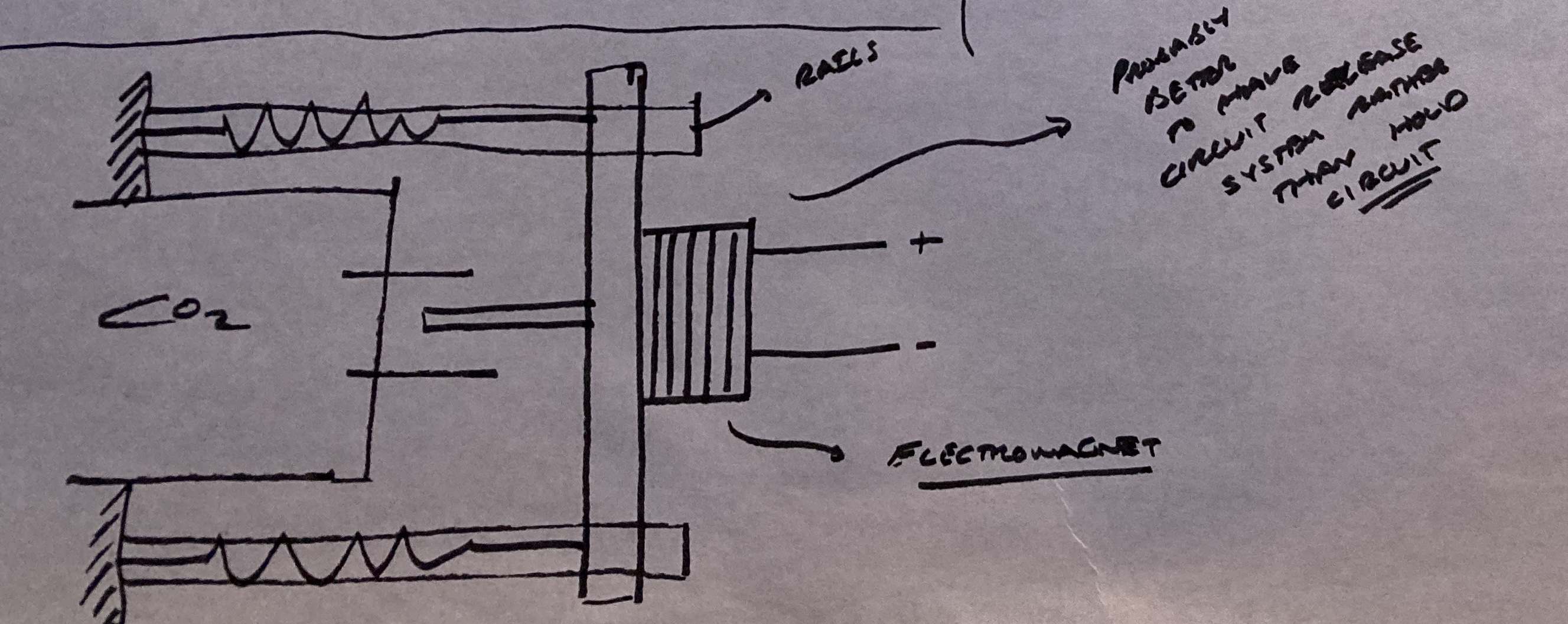
V1 (Left) : The first version utilises a set of 2 square rails on either side of the CO2 canister. An electromagnet in the form of a solenoid, is wrapped behind the firing pin, which in itself is magnetic. The solenoid is activated causing repulsion sending the firing pin into the CO2 canister. A pairs of springs mounted on either side of the rail, pushes on the firing pin assembly thus ejecting it.
Advantages: (1) It punctures the CO2 canister relatively simply. (2) It would probably require less current to carry out the pierce as compared to the linear actuator. (3) It also ensures no choked or blocked flow. (4) It would be very easily repeated as a whole unit. (compared to the linear actuator however, it isn't as modular and extendable.)
Disadvantages: (1) It requires current to be held, in order to overcome the compressive reaction stress from the springs, this means that the current requirements may be higher than required, especially since the force on the spring increases with deflection. (2) Will the high pressure stream from the CO2 canister be so great, as to perhaps break of permanently deform the springs, making the system not reusable? (3) What kind of pin will be required, might it be too fragile and not puncture the CO2 canister.
V2 (Right) : This is a variation of V1, in that the firing pin is attached inside a solenoid to conducting rails. The solenoid activates and repels the magnetic firing pin once more into the CO2 canister. Graphite is used on the rails and thus allows it to conduct. This allows the rails to serve as a direct connection to the solenoid, thus simplifying the design. It also lacks the springs in V1 reducing the force required to get to the CO2 canister. Also in having a flat design that is one piece to wrap around the rails means that it would be significantly easier to manufacture.
Advantages: (1) As above, it doesn't choke or block the flow. (2) The design has been made more streamline allowing it to be manufacture easily and as a more reasonable design. (3) Being inside solenoid means that the repulsive force would be greatest, because it begins in the space where the electromagnetic field strength is greatest, thus increasing the possible force produced. It also passes back through the solenoid which may be able to slow it down by Lenz's law.
Disadvantages: (1) It is still significantly more complicated compared to a linear actuator. (2) Though requiring current to be applied as one quick pulse, lowering stress on the electronics department, the design still doesn't provide any clear benefit over an actuator. (3) It has a great dependence on DIY components, which means that the tolerance of failure will be significantly greater than the actuator which is made entirely of COTS components.
- Firing Pin through Solenoid.
- Rotational Piercing: These are a series of designs that revolve around using some rotational mechanism to pierce into the canister. The thought process behind using these methods is that it is analogous to a power drill, which is a very simple and reliable device used to create holes. Moreover, using a rotational mechanism simplifies the electronics behind because a simple DC motor simply rotates and then can easily rotate in the opposite direction. Unfortunately, these designs if they were to be expanded to take multiple CO2 canisters into consideration it would either require more motors which would tremendously increase the cost of the design, or gearing which would increase the complexities involved.
- Holding CO2 in a reservoir
Disadvantages: (1) it involves pre puncturing a CO2 canister, this means that there is no
- Purely Mechanical
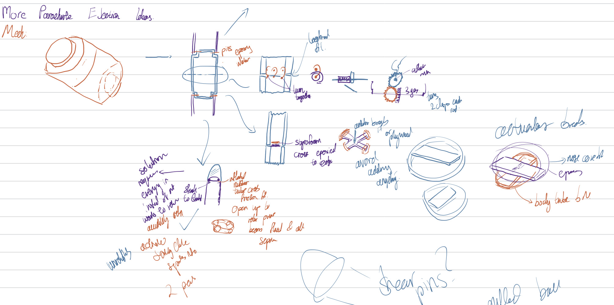
Ideas 1, 2 and 3 all reference the above image.
- Hooks (not versatile)
General: Hooks is a possible suggestion in which a separate 3D printed body tube is manufactured, it is manufactured to the same dimensions as the body tube and slides into the nose cone and the main body. This serves as an interface in which any mechanical release mechanisms may be integrated. This 3D printed section (the interface) is split into two sections. Here, in this hook design a series of 4 clasps are assembled around the body tube, each having the hook connected to the lower body tube and a pin to hook onto connected in the upper section (See the top drawings and their train of thought). The fit between the two interface sections is a locational fit, meant just for holding them in place without providing any resistance. This means that the hooks hold the section together in all its entirety.
How: When parachute ejection occurs, the hooks are swung back using a motor, which is connected to two perpendicular shafts. Thus when the motor turns, it causes the hooks to release from their separate pins taking apart the two sections, using the force of gravity to pull them apart.
Advantages: (1) It seems easy enough to make, (2) it uses only one motor and (3) it would probably be quite cheap.
Disadvantages: (1) It needs a separate interface 3D printed for each rocket hence the lack of versatility. (2) It seems like a rather flimsy connection between the upper interface and the lower interface, thus there is no real way to stop it falling apart mid flight. (3) Are 4 hooks really enough. (4) Using a gear mechanism to control 2 perpendicular shafts is bound to add unneeded complexity. (5) How do you connect the hooks in the right place before take off? (5) where would the parachutes go?
- Breaking Panels (not versatile)
General: This one applies in the similar way to hooks a separate interface section, without any real frictional fits between both parts. This idea uses a series of cheap plywood/Styrofoam connector parts, to connect the two interface sections together. These are cut as a series of 2 rings with a line in the middle, that are placed on top of each other The outer edge of the ring is glued to the inner body tube. The 2 inner bars are glued together in the middle. The wood or styrofoam is thin and thus weak. Small cuts or slits could be made to make it weaker and more brittle. A schematic is the middle train of thought.
How: A linear actuator punches the central component with sufficient force so as to break the bond. This separates the 2 interface components, allowing the rocket to break into two. This works because the top ring connects to the top interface part, and the bottom does that for the bottom interface part. The rocket just falls apart under its own weight
Advantages: (1) It seems really easy to do, all it needs is an actuator and some laser cut plywood. (2) It would be really cheap because a small actuator is all that is needed (3) Because it is rings, there would be enough space for a parachute.
Disadvantages: (1) This is a really outlandish, borderline crazy idea. (2) It is not necessarily reusable you would need new panels every time. (3) It needs new plywood cut for each rocket. (4) How would you remove the stuff inside the rocket post recovery? (5) Is there enough thickness to create a proper bond between the rings and the interface. (6) What guarantees are there that it would break into two parts. (7) Because it breaks into small pieces, how do you prevent it being dangerous to observers from the ground?
- Rubber Diaphragm (possible?)
General: This is the most practical and most realistic of the first 3 ideas suggested. The others are a bit zany. This one doesn't require a separate interface, contrary to the image above. In this design there is a rubber diaphragm like a balloon or something: basically, something that can inflate to a large enough size. It is filled with air. It is glued to small shoulders located at the top of the body tube. It slides into the nose cone. There is no friction fit between the nose cone and the body tube, the diaphragm, serves as the de facto body tube. Follow the third train of thought from the top.
How: At separation, the diaphragm would be deflated, this could be achieved by opening a valve. Now that it is smaller, there is no effective friction fit between the nose cone and the body tube, thus they are two separate entities and can fall apart.
Advantages: (1) It is simple. (2) It seems actually doable, (3) There are few mechanical parts aside from the solenoid valve, thus nothing really can fail. (4) There is no chance of pressure leaking because the gas inside is not high pressure. (5) It would be easy to assemble pre-launch.
Disadvantages: (1) This involves taking energy out of the system, because this is a process that nature naturally subscribes to, it may be a bit difficult to prevent an early release.
- Quick Release System (possible?)
¶ Brainstorming (23/03/2021)
- The second meeting we focused on the design of the spike to puncture the canister, brain stormed some ideas will upload later.
- We also thought about the possibility of N2O canister instead of CO2, lesser pressure maybe get back to using solenoid valve? Also easier to puncture, got foil on top look very fragile.
- We also thought of using recreational culinary nitrous oxide canister ideas, which involve screwing around it and then unscrewing it. (May have some problems to get a hold of them.. because of other purpose.) Easier to puncture.
- Both were considered possible after consulting electronics folks.
- Diagrams links and more to come.
Autogenerated on 2022-06-10 using 1337 h4xx0r 5k111z, from ye olde Confluence Wiki
Old Metadata: Created by Ting, Jayden, last modified on May 15, 2021
ID: 261104092