Background
One of the main objectives for the fin mount design for Sporadic Impulse was for the fins to be removable. Having removable fins means that they can easily be redesigned and replaced for each launch depending on centre of pressure requirements. It also means that any damaged or deformed fins can be removed and remanufactured with relatively low cost as it does not requiring complete replacement of the fin and fin mount assembly, as seen on other high powered rocket designs.
My original designs were based of the fin can design used in A.P.O.G.E.E Heavy and November Rocket. These rockets had solid fin cans which made up the entire bottom end of the rocket and housed the motors of the rocket. The fin can was entirely 3D printed and also had removable fins. However, this was not suitable for Sporadic Impulse as the hybrid engine much more powerful than the COTS motors used in A.P.O.G.E.E and November Rocket. It was not possible to 3D print a fin can to the size required for Sporadic Impulse and it would also have been incredibly heavy.
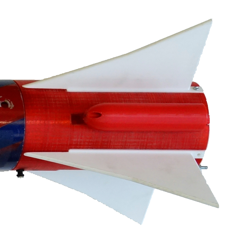
The new fin mount designs were designed to be much more low profile and to attach to the exterior of the lower body tube, rather than actually being the lower part of the rocket. This means that it is more of a separate component that does not rely on the mounting of the hybrid rocket engine and hence reducing the complexity of assembly. The fin mounts can be permanently attached to the outside of the lower body tube prior to launch day to reduce assembly time.
Design
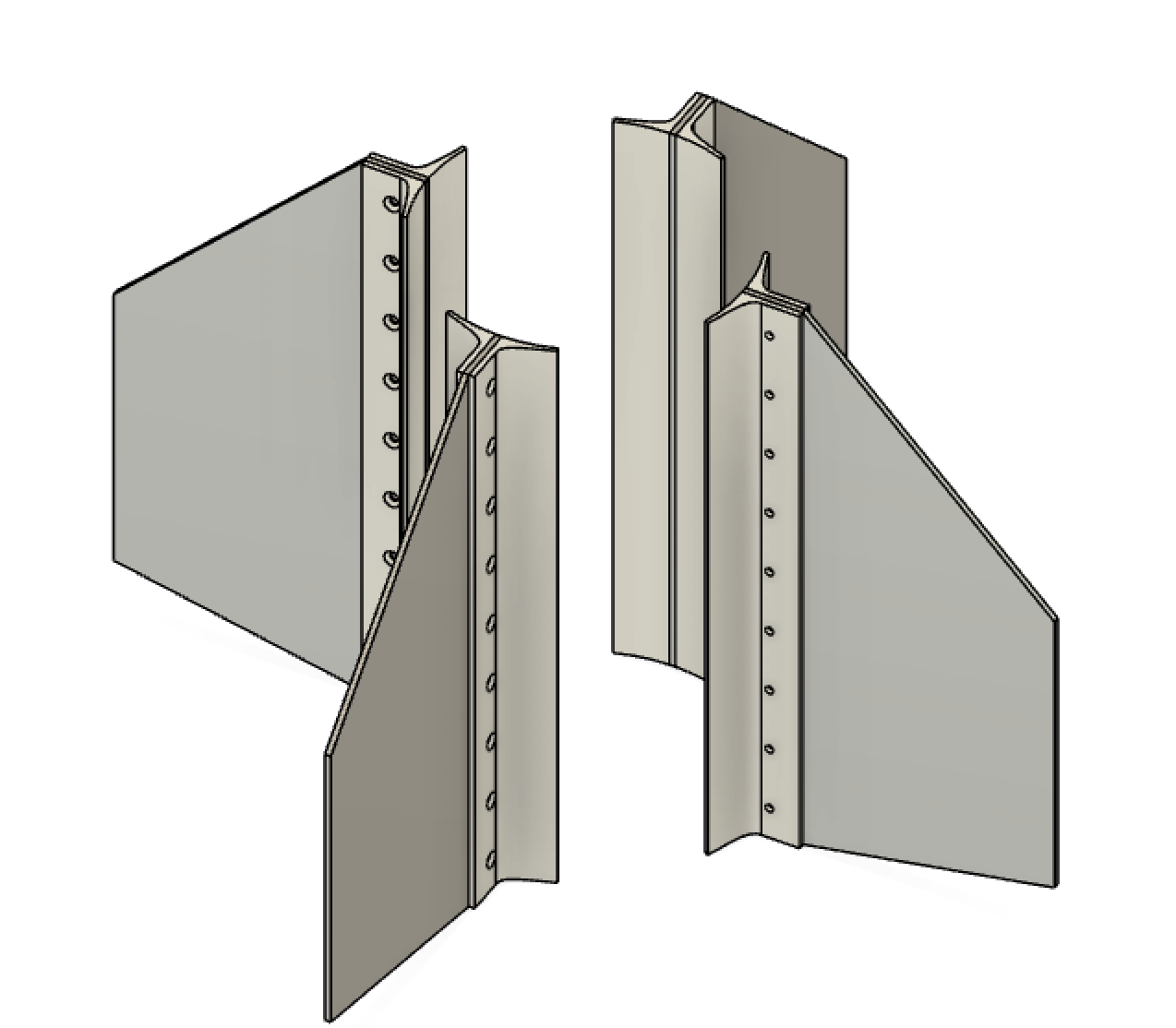
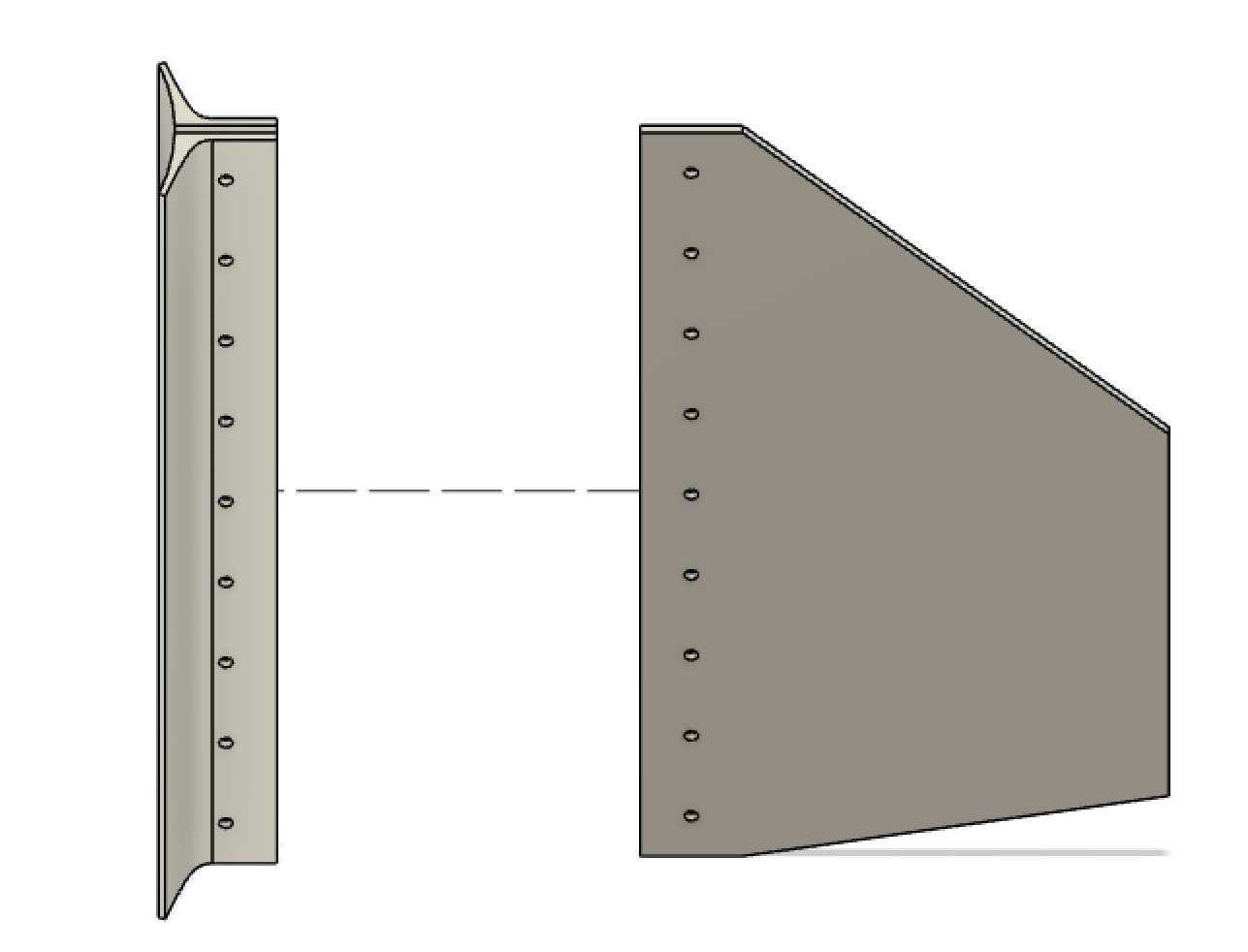
The fin mount design is composed of external fin rails made of 3D-printed ABS plastic which are epoxied to the outer surface of the body tube. Each rail is made of two parts. There are 8 M5 holes in the rails spread evenly across its length. The rails are attached to the body tube so that there is a spacing of 3mm between them for the aluminium fin to be sandwiched in-between.
The fins are trapezoidal flat plates made from a sheet of 3mm thick FR-4 fibreglass. A trapezoidal design was chosen as it is a popular fin shape and is easy to manufacture. The dimensions of the fin are a root chord of 290mm, tip chord of 150mm, semi-span of 130mm and sweep angle of 45 degrees. These dimensions are based of OpenRocket simulations and are adjusted to ensure the correct centre of pressure, aft of the centre of gravity to ensure the correct stability of the rocket.
The combined mass of the fins and fin mounts come to 1.718g with nuts and screws included.
Development History (from 17th Oct onwards):
7th November 2020
- Hole size changed to 5mm from 4mm to help reduce stress at fin mount holes
- Fin mount curve change to account for larger 9.5mm diameter screw heads
- Hole distance from edge of fin mount decreased (now centred with flat part of fin mount)
9th November 2020
- Fin flutter study was conducted using MATLAB, showing that the fins will not experience aeroelastic fin flutter during flight
17th November 2020
- Fin mount design change - sunken screw heads for greater aerodynamics and reduced drag
- Curved leading edge of fin
- Hole distance from edge of fin mount increased back to previous state
20th November 2020
- Change to G-10/FR4 fibreglass fin
28th November 2020
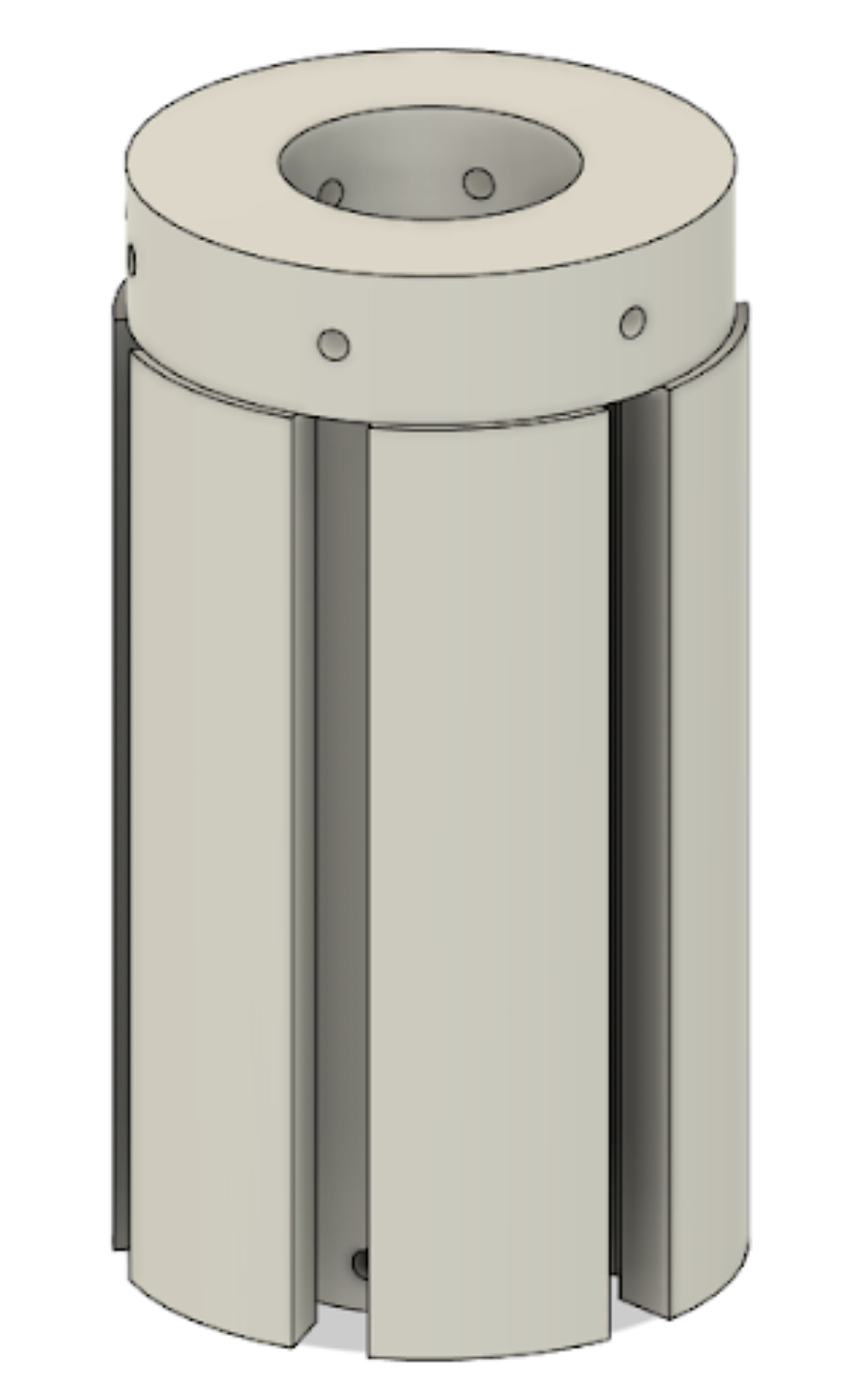
- Fin rail nose cone created
- Removed washer and reduced screw length
5th December 2020
- Reduced nut height so that they no longer stick out
- Reduced screw height
- Reduced number of screws to 8