¶ Servo/Solenoid Test box
Technical Lead : Riley
Priority : Nice-to-have
Since we will be moving the majority of the testing electronics to Silwood, it is neccesary to make a dedicated kit for testing propolsion components in the workshop. This box is for testing such components, specifically servos and solenoids.
It should provide both a hardware interface (over swithces and dials, with a screen readout of angles and control) and a software interface over grafana.
¶ Tasks
-
Design 3d prints for mounting the displays and switch (plate is 6mm thick)
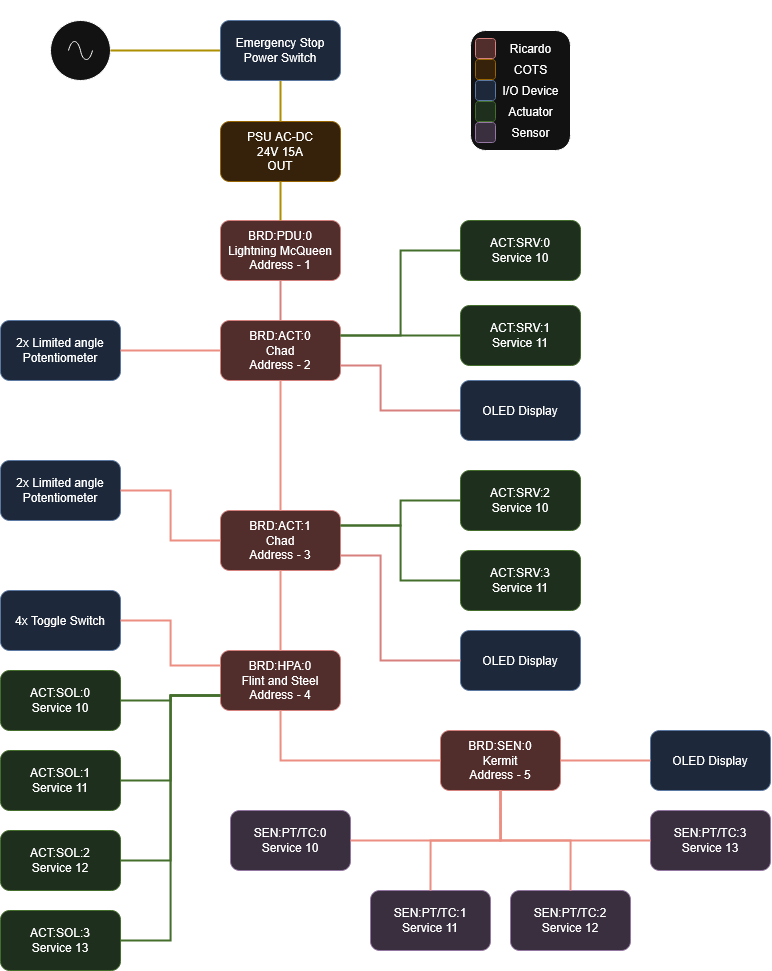
Create a draw.io diagram of the servo test box hardware. It should be built to the following specifications:
¶ Specifications
- It must be able to simultaneously control 3 solenoids and 3 servos.
- Users must be able to control the servos through limited angle dials.
- Users must be able to control the solenoids through switches.
- Users must be able to access servo and solenoid deployment information through a built in screen (servo angle, solenoid state + any other info).
- Users must be able to control solenoids and servos through Grafana.
- Users must be able to have access to 4 PT/TC measurements
Diagram should show how all of these features work and how each component is driven. Check out Flint and Steel and Chad for solenoid and servo control respectively. Assume that the servos and solenoids are compatable with these boards. Also, check Kermit for control over the pressure transducers.
Use CAD to design the physical layout of boards and interface within the workshop test box.
- In CAD, import 3D models of all the boards needed for the test stand + any other COTS components (dials + screens)
- Once the rough aspect of the test box has been created, find a suitable Aliexpress Pelicase to fit everything in.
- Once pelicase found, design a side panel and a top panel in CAD that can be lasercut / printed, the side panel should contain the sensor patch panel, and the top should contain switches, displays, power switch, etc. The pelicase doesnt need to be imported but you will have to create a 3d box of reasonable dimensions.
- Review design with project lead.
¶ Resources
Link any resources here, i.e. other diagrams, schematics, online articles / designs.
Pages 21-27 of Pluto’s Technical Report contain useful information on many of the circuit boards used.
Files and other resources for this project can be found in the ICLR Teams Group.
¶ Bill of Materials
1x Pelicase Color: 346x250x136mm (Internal: 300x200x95mm)- One of these from Aliexpress (when purchasing make sure to pick the right one)
1x Power Supply Unit - Acquired
1x Lightning McQueen PCB
2x Chad PCBs
1x Flint & Steel PCB
1x Kermit PCB
1x DC Transformer - Acquired
4x Potentiometers - Acquired
5x Toggle switches - https://www.switchelectronics.co.uk/products/on-off-spst-toggle-switch-250v-ac-15a
1x E-Stop Button - Acquired
3x OLED SPI displays - Either Simpler 2.23" 128x32 4Pin White OR More complex 2.7" 256x64 7Pin
8x 3-pin aviation connectors
4x 4-pin aviation connectors
~16x 3-pin nano female connectors
~8 meters of wire
Extra materials:
Top (inside) and side panels.
Insulating material to attach boards to.
A servo, solenoid, PT and TC for testing purposes.
4x Covers for the potentiometers.
¶ Notes
Section for miscellaneous notes related to the project, or ideas for the next version.
To meet the specifications, the box will need to contain at least two Chads, one Flint and Steel and one Kermit.
I/O Devices:
4x toggle switch (see-saw type)
4x potentiometer similar to this one but with a ‘D’ top
1x E-stop power button
3x OLED SPI displays
Power requirements:
Solenoids: 12-24V @ 2A
Servos: 5V @ 3A
PT/TC: negligable
Power supply: 24V 15A
Below is the draw.io diagram to represent hardware in the box: