¶ Capacitive Fill Sensor
Technical Lead : Jack
Priority : Nice-to-have
To detect the level of fluid in a tank that we cant see in-to we can measure the mass or measure the height of liquid. Mass is useful for filling but after there is fluid in the feed system then it becomes less reliable so a capacitive sensor is needed.
This will involve design of the physical capacitance plates, designing a capacitance to voltage/current converter board, integrating it into the kermit sensor suite.
¶ Tasks
- Develop the sensor hardware
– Determine what materials to make the two conductive plates.
– Cad the Sensor.
– Manufacture the sensor.
– Verify capacitance with sensor, bucket of water (or whatever useful) and multimeter. - Develop the daughter board PCB
– Design board for capacitance to voltage/current conversion.
– Test board with low capacitance capacitors. - Write calibration code for Kermit.
- Validate on tank.
¶ Resources
Cap Fill explaination. (bit quirky of a guy but seems legit)
At a very high level, were taking a square voltage wave (±6V), differentiating it using (1), into a spikey current signal. We then convert this using (2) into a spikey voltage signal. We pass this spikey voltage signal through (3) which rectifies it into a voltage signal that is only positive and not negative. This can then be smoothed by (4) to get a stable voltage as a function of capacitance.
¶ (1)
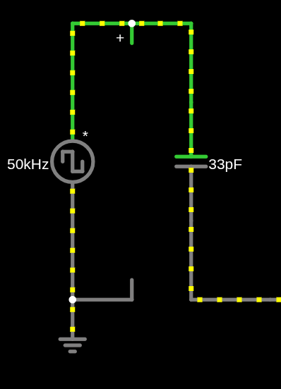
This first part of the circuit converts the excitation signal into a current measurement. When the square wave goes from low to high voltage, this creates a very large dV/dt. Since the equation for current through a capacitor is I = C dV/dt, a large dV means a large current spike.
¶ (2)
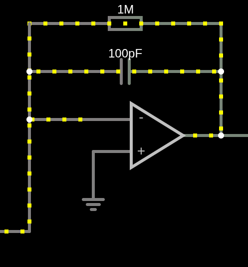
This next section is called a Transimpedence amplifier. This takes in a current spike and turns it into a voltage spike.
An ideal transimpedence amplifier looks like : -I_in * R = V_out.
Because op-amps are assumed to have 0 current draw at the inputs and the inverting node is acting like a 0v reference here, the current passes through the resistor and since v=ir displays a voltage on the output of the op-amp, only dependent on current into the sub-circuit.
Good vid on op amp circuits
¶ (3)
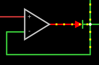
This is known as a precision rectifier. It gets over the fact that diodes need a small starting voltage to allow them to conduct (forwards voltage) as this may be bigger than our signal. This means that the V_out is only ever seeing the current spikes that are positive as the diode stops it from reversing the current flow.
¶ (4)
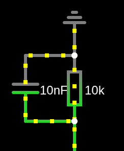
This then smooths the wave we have created into a DC signal from AC.
Things to note that i got confused abt when trying to document this:
If you remove 4 from the circuit the output looks like a squeezed square wave. I think this is just non-ideal effects from the falstad diode model.
¶ Notes
Design requirements are as low mass as possible and the full length of the fuel tank: (not known yet)