¶ 1. Introduction and Context
For electromagnetic separation, electromagnets are used to facilitate separation. Due to the repulsive as well as attractive abilities of an electromagnet, multiple variations of electromagnetic separation exist. For example, 2 electromagnets could be used in tandem with both of them attracting one another and then the electric current could be switched off, causing separation. Another approach is to have two components fitted into one another using interference fits and switching on an electromagnet, causing repulsion separating the 2 components. The third approach which was seen in [1] outlines an approach in which both the repulsive and the attractive abilities of an electromagnet are utilised.
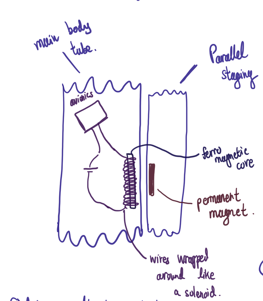
In [1], a permanent magnet is used together with an electromagnet. Prior to separation, the permanent magnet is attracted to the soft iron core of the electromagnet. At separation, a current is passed through the electromagnet's coil, this replaces the attractive force with a repulsive force. Said repulsive force causes the separation. However, in [1], parallel staging was employed. Encore uses direct staging, thus the concept is retained however, a new set of equations is required.
¶ 2. Original Concept conversion
To convert the parallel staging concept that was employed, the main change is that the magnets had to be orientated vertically as opposed to horizontally. The issue with this, is that this introduces a frictional force in the friction fit, which must subsequently be tied into the calculations.
On top is a diagram of [1]'s approach, they used simple electromagnet coils adjacent to a medium sized Neodymium Magnet. In the revised approach for direct staging, below, the electromagnet and the Neodymium Magnet are placed vertically in line with one another. They are situated within a friction fit. The Neodymium Magnet is retained because Neodymium magnets are affordable, being priced between £1 and £20 per unit [2] as well as one of the stronger permanent magnets available[3]. The electromagnet however, is entirely variable because often electromagnets that are sold are very thin, also the specifications present for electromagnets are difficult to find on the internet.
¶ 3. Orientation of the Magnets
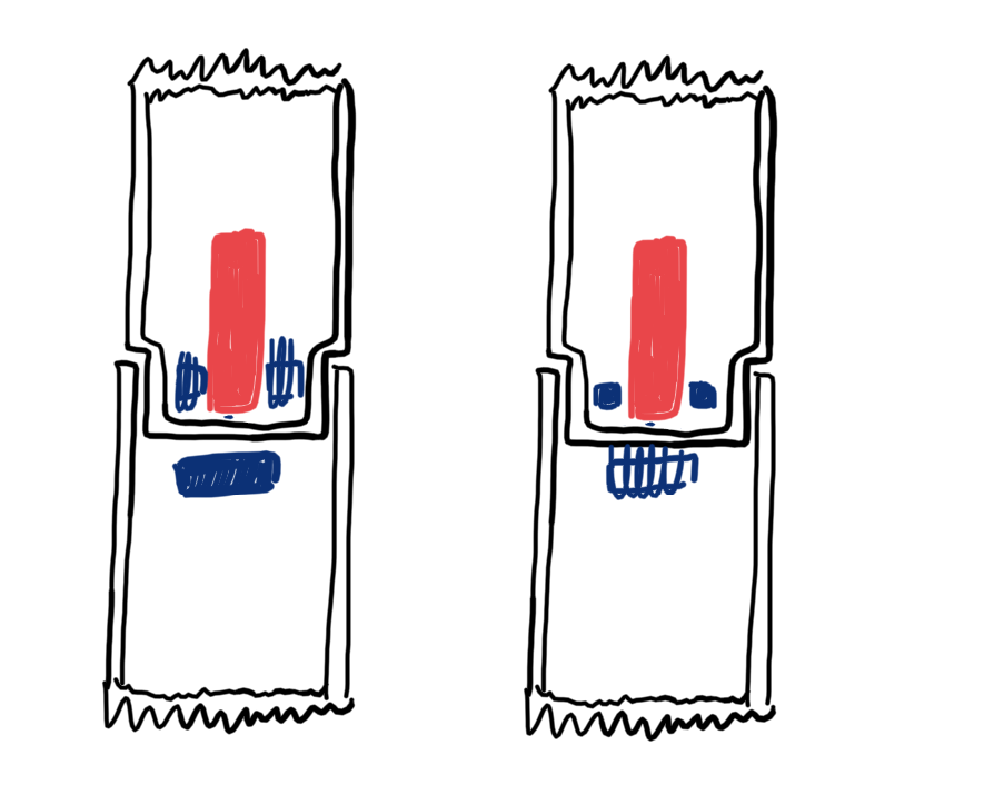
An issue of significant concern, for the electromagnetic separation is the orientation of the magnets, i.e. whether or not the electromagnet should be located in the second stage(left picture) or in the first stage(right picture). The factors to consider are (A) whether or not there are any electromagnetic effects on the rocket motor itself, (B) whether or not the electromagnet affects electronics, (C) how many avionics bays are needed and (D) are there any thermal effects of the electromagnet.
(A) The contents of the motor are rocket fuel and the oxidiser [4]. The oxidiser is traditionally nitrogen dioxide, this doesn't contain any magnetic substances, and thus will not be affected. The rocket fuel is normally comprised of Charcoal, Sulfur and Potassium Nitrate. All of these components have magnetic susceptibilities, which are either negative or of the order of 10 to the 6 [5][6][7]. This means that these substances may be considered non-magnetic, thus there would be no magnetic effects. The motor casing is made of aluminium, non ferromagnetic and thus would not be affected. However, there is one steel screw in the top of the motor, this may cause effects, but it is unlikely.
(B) The printed circuit board, is located sufficiently far away from the relatively small electromagnets, this means that the magnetic field will only barely reach them at most. Thus causing limited disturbance.
(C) If the electromagnet is located around the second stage motor, this means that only one avionics bay is required, because said avionics bay also triggers the activation of the second stage motor as well as the electromagnet. That would also control the parachutes, which might be a lot of pressure on the electronics there. Alternatively, if the electromagnet is located below, another avionics bay is needed, perhaps it could be integrated with the parachute deployment of the first stage.
(D)The motor is encased inside an aluminium motor casing, this means that there is very limited heat transfer through the casing, to the magnets themselves, so thermal effects are negligible. This was only put here because of knowledge from A levels saying that high heat demagnetises magnets.
However, by Newton's third law, the force applied from magnet A to magnet B is the same as the force applied from magnet B to magnet A, with opposite direction, this means that all calculations remain valid.
¶ 4. Determination of the current required for the magnets
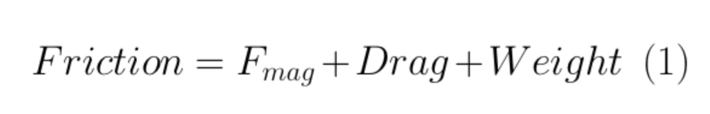
To determine the current, required, it was modelled that the most significant forces were the friction from the friction fit , the weight, the drag as well as the magnetic force . Consider the free body diagram.
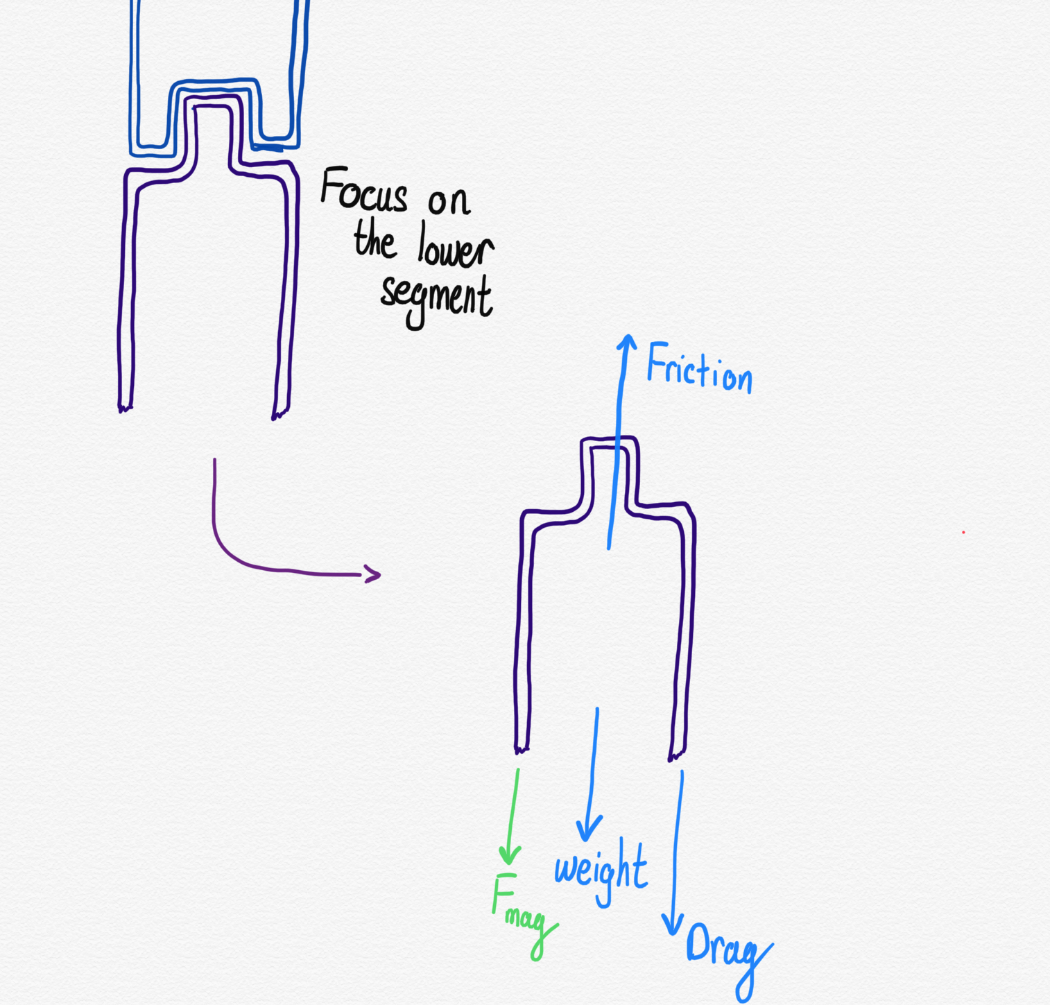
So the added Magnetic Force, F mag , should break the equilibrium between the friction, the weight and the drag. For that to happen, take it as the point of limiting equilibrium with the magnetic force. So that a minimum value of F mag , can be obtained. Due to the fact that the value of the current obtained would be an approximate value, any current that is higher should be sufficiently high to separate the two bodies. For example, if the requirement is 3.4A, it would be unfeasible to obtain the exact value and 4A could be taken which would be more than sufficient to cause repulsion. This calculation does not take into consideration the attraction added to the system by the permanent magnet and the soft iron core. This is not included because that would increase the upwards force, however, because it is replaced with a greater vertical repulsion force. Thus it would technically 'increase' the magnetic force pushing down because the upwards force is of a smaller magnitude. Thus this case is seen as more of a worst case scenario.
 4.1 Approximations
(1) For friction, the appropriate calculations for a friction fit are applied. The fit is taken to be a locational interference fit. This means that it is given the designation H7/p6 and P7/h6. If the inner tube radius, a, is taken as 53.5 mm, a maximum interference of 11 μm is obtained. Assuming the tube is made of 1.5 mm thick plastic like polyethylene, it would have a coefficient of friction, μ, of between 0.2 and 0.4 [9][10], assuming a ordinary scenario, where it is dry and clean, the value of 0.3 is employed. For Young's modulus of a standard plastic like polycarbonate, the values are highly varied, ranging from as low as 2 GPa [11][12][13] to as high as 20GPa[14], considering, that the vast majority of sources came to the conclusion of approximately 2 GPa, that is the adopted value. Now, when added to the appropriate calculations, a Friction force of 28.2691 N is obtained.
(2) The Drag force is taken as 10 N from analysing, the graph of drag force against altitude for a small scale model of Encore. The 10 N was chosen from a small cruise section because it is a representative value of the friction. Considering that at separation, the drag would be higher, this is taken as an underestimate. Hence preventing an insufficient magnetic force.
(3) The weight is taken of the lower section, which is taken without the mass of the magnets because it is possible to buy very small, very powerful magnets. For example, it is possible to purchase 4 magnets with a 2.2 kg pull and 10mm x 10mm x 3mm at a price of £10 for 20[15], with a mass– taking the density of neodymium as 7.5 kg m -3 [16][17]– which gives a mass of approximately 9g. If a larger whole magnet is taken, a mass of 400 g is more likely– that considers a 60 mm diameter magnet which is 5 mm thick. Thus if the mass of a rocket motor and motor casing is taken, the mass is approximately 1.2 kg. This leads to a weight of 1.2 x 9.81. i.e. 11.772 N.
(4) The magnetic flux density of a neodymium magnets is taken as 1.1 T[18]
¶ 4.2 Calculations
From this, it concludes that F mag should be 28.2691 - 11.772 - 10 i.e. 6.4971 N.
Now, if that is substituted into the Maxwell pulling force calculations, equation (2) is obtained. This can be rearranged into equation (3). Thus an expression is obtained that evaluates the current– I–, using the contact area between the 2 magnets– A–, the number of turns– N– and the length of the coil– L.
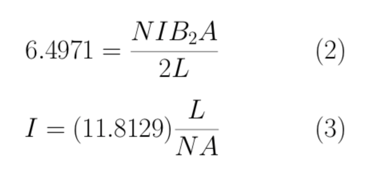
If the case is considered where a coil of length 20 cm is used– to obtain a coil of length 10 cm a diameter of approximately 3 cm is needed– with 50 turns, If the area is taken as the maximum area possible, this would be the 10.7 cm internal diameter minus the 3.84 cm rocket motor casing diameter. The area would be 7.8339 x 10 -3 m 2 . The necessary current is 3.01584 A, which is probably veering on the dangerous side. The number of turns and the length of the coil need to be varied in order to lower this number.
Updated 6 February 2021
The designation of the topside being designated for the electromagnet, is actually a flawed idea because that considers that the contact area between the magnetic fields is equal to the length of the coil as opposed to the internal area of the coil. Thus the design which is actually finalised is using the electromagnet at the bottom and the permanent magnets, 8 of them surrounding the motor. This is deemed as the best way to be able to maximise the contact area between the 2 magnets, because if the electromagnet were situated around the motor casing, it would prove difficult to fit. In its alternative arrangement it provides greater flexibility if one wants to use it with or without a core (as shown below).
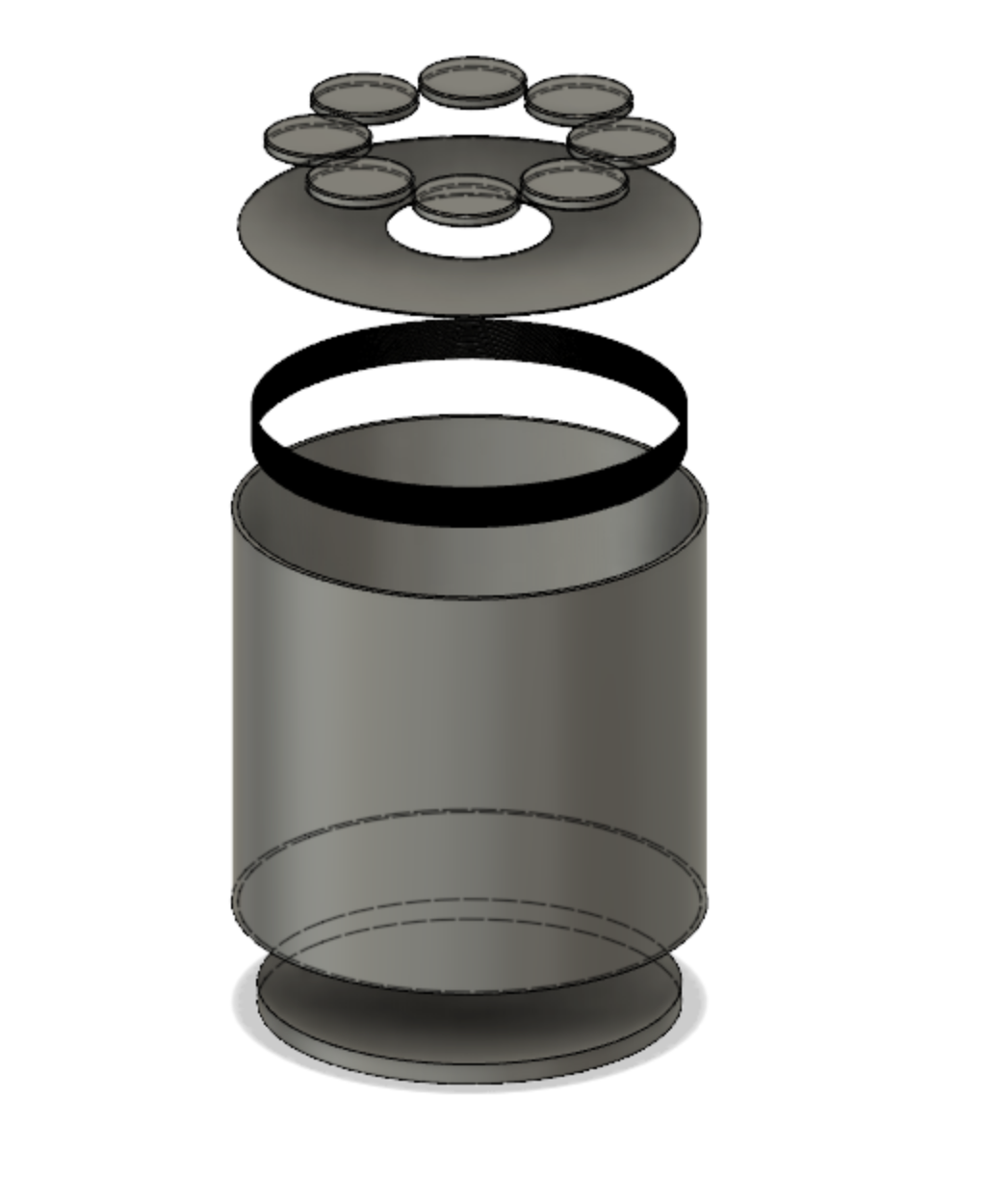
It has been established that in going forward with the designs, the magnets that a custom made electromagnet would be used from 0.2 mm diameter copper wire surrounding an iron core of diameter 100 mm. For weight reasons, this iron core proves optional, it has a weight of approximately 600g, which is too great for model rocketry. That is because the iron core's original purpose was to serve as a means of attraction in order to hold the 2 layers together, however, with the presence of a coupler as seen on the Open Rocket document, this renders that unnecessary. So, instead the copper wire solenoid will generate a magnetic field that will repel the permanent magnets: separating the 2 stages. The permanent magnets will still be neodymium magnets with a diameter of 25 mm and a thickness of 3 mm[19], these proved to be the best fitting magnets for the case.
Practically, the numbers have varied slightly in that a lower magnetic force is required. The above calculations estimate for a strong locational interference fit between the interstage and the second stage, however, in reality, with both components being made from body tube of the same diameter and a coupler connecting the two stages. Therefore, the above calculations still hold valid because they overestimate the magnetic force required for separation.
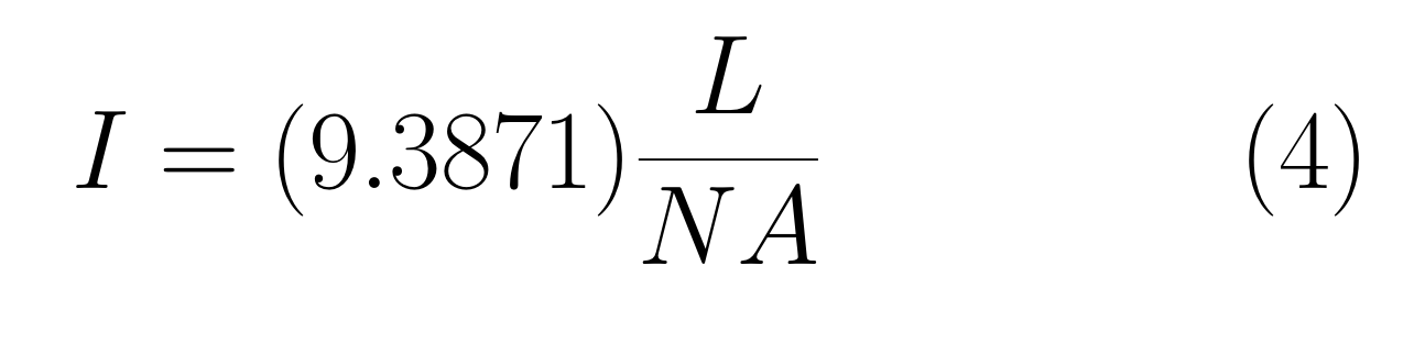
Due to the refreshed arrangement of the electromagnet system, this has meant that the areas lengths as well as number of turns has changed slightly. The subtle changes mean that the L becomes 10 mm and assuming that the number of turns is at a maximum, N = 50. I was then calculated for two different cases, maximum and minimum area. this is because the actual value is likely to lie within these two boundaries. The upper boundary for area is from the area of the electromagnet, the lower boundary is the area from the eight permanent magnets. The current is therefore 0.30081 A ≤ I actual ≤ 0.60163 A .
T aking, the resistance of copper wire as 205.7 Ω per 1000 ft or 304.8 m [20], this obtains a total resistance of 10.601 Ω and thus a voltage of 6.3777 V, this is less than 9 V, and thus makes it entirely possible for a 9 V battery to supply the necessary voltage in order to separate the two components.
The main concern however is the mass. If the mass of copper wires is taken as negligible that means that the major mass from this area is actually due to the 9 V battery, the permanent magnets and the electromagnet. This is why the iron core was deemed as optional because the iron core is not considered in the calculations for magnetic field strength and also the components are close enough so that it shouldn't cause too much of an issue. The iron core resulted in a mass of 618.11 g. Thus the mass of the assembly with the iron core would be 789 g, which is too large, without the iron core, the mass becomes 171 g, which is possible for a model rocket.
Updated 16 February 2021
Following discussions on Saturday, the interstage will be fitted inside a tube coupler. For Encore, the tube coupler has a diameter of 3.78 in. (9.6012 cm) and a thickness of 0.062 in. (0.15748 cm). When inserted the frictional forces changes to 14.9639 N (everything else remains the same), the fit was also changed to H7/n6 (originally, a H7/k6 was chosen however, this decreases the magnetic forces too greatly, so the passive drag forces around it would overcome the separation, rendering the electromagnetic separation useless and making it uncontrollable when separation occurs), which is a locational transition fit[21], this allows it to make up for the decreased magnetic force. This means that the Magnetic Force required would change, it decreases to 26.9349 - 11.772 - 10 i.e. 5.1629 N . Mass calculations do not vary because the change is minimal, so the approximation of 300 g, inclusive of the electronic staging bay is still more than ample for the interstage section.
The equation becomes
This means that the currents are about 90%, of the originally calculated currents. Thus making operation overall safer.
Updated 6 March 2021
After the design review with Dr. Knoll, some key aspects were highlighted which needed further analysis.
(1) - Will it be magnetised to the motor casing? - This was seen as a simple check as bringing a bar magnet close to the motor casing and seeing if any attraction occurs.
(2) - Will the needs of the egg timer current, voltage output, etc be sufficient to power the electromagnets?
(3) - A 9V battery doesn't supply enough power and capacitors may have had a few problems, therefore what about the feasibility of a Lithium Battery?
(4) - The potential need for electromagnetic switches (auxiliary power and a transistor needed as well) or solid state relays (really expensive).
Some of my other concerns in the design are raised below.
(5) - Will the lack of a core in the electromagnets be of great detriment to the design?
(6) - Exact current output.
(7) - Exact mass.
(8) - How much will the apparatus cost?
(9) - How will it be manufactured?
(2) Needs of the egg timer.
The egg timer that has been chosen for the electronic staging bay, is identical in model to that chosen in the main avionics bay. It is rated with a current output of 8A and a voltage output of 60V. Considering that the maximum power output is then limited at 480W, it seems that the flight computer has more than sufficient output power to handle with the demands of the coil, providing an extra order of magnitude of buffering.
(3) Lithium Battery possibility
A lithium battery that can be purchased can have a rating of 1.5 Ah, as well as 32 V and a max current output of 4.5 A, the maximum power here is 144 W, though less than the maximum power output of the egg timer, it still remains an order of magnitude higher than the power required for the electromagnetic separation. This means that a Lithium ion,, considering a pricing of £ 6.76, seems like a highly feasible option without incurring an excess of cost, moreover, it has a comparable mass to a 9 V battery (Li - ion 42 g, 9V - battery, 45 g).
(4) Electromagnetic Switches and Solid State Relays
The electromagnetic switches and solid state relays were mainly considered in the event that the egg timer was unable to supply the necessary requirements needed for an electromagnetic coil. However, given the fact that the egg timer with a lithium battery can supply more than the excess power, neither option seems necessary: a circuit that includes both the lithium battery and the egg timer along with the coil should be sufficient.
(5) The lack of core & (6) Exact Current Output
The main issue with this part is that generally most electromagnets have a coil within them, and considering that the calculations here are based on a typical electromagnet, the magnetic repulsion force may not have been sufficient, this is especially due to the fact that an iron core strengthens the produced magnetic field. Additionally, the lack of core would have made it very difficult to manufacture, because it would have ended up most likely not circular. This creates a problem because too large of an iron core would mean that the mass of the section would become highly detrimental as shown above; a lack of core may not be strong enough; if a small core is used, then the electromagnet's surface area becomes too small, and by the above equation, the current increases significantly.
This is why a solution was developed, which solves another problem: the fitting of the motor casing. By using a series of screws with coil wrapped around them mounted to a plywood ring, similar in manufacture to the permanent magnet arrangement. Each of the screws would have 6 layers worth of magnetic copper coil wrapped around them and they would positioned in a circular pattern. This solves the need for an iron core: the screw now, it makes it easily manufacturable, it also doesn't increase weight significantly. However, this raises an issue in that the coils may be very close to one another and their magnetic fields could interact and cancel each other's effect, however, given that a stronger magnetic field will be generated it should be alright. The other issue raised is that of connecting each of them to one another in a complete circuit. this will be achieved by wrapping each with an individual wire strand for the 175 vertical turns, 6 times thickness, the ends of the wire will then be on the top of the plate and an additional wire connected to the main section will attach to each of these exposed ends.
Using this configuration of 4 cm screws wrapped in copper enamelled wire, with 6 layers of 175 turns, creates 1050 turns per screw. This requires a maximum current of 0.45472 A, using the area of the electromagnets and a m inimum current of 0.079680 A , considering that this is less than the originally intended value, it should be more than sufficient. The resistance is calculated as 1.1935 Ω (there are 2.232 m of wire) , the power is thus estimated as 0.39079 W using P = I 2 R, once again this lies in the necessary boundaries. This all means that, though it would require significant work to wrap around each of the coils, it serves as a better design, by allowing the motor to slide through the assembly as well as lowering the required current.

Top:
the new electromagnet configuration, it has 16, 4 cm screws each wrapped in 0.2 mm copper enamelled wire.

Bottom: the revised arrangement within its tube coupler.
(7) Exact Mass & (8) Exact Price (updated)
Exact price is £82.17 inclusive of egg timer and 9 V battery (both of which are mentioned because they are most likely already in possession of ICLR).
Exact mass is 420.90 inclusive of staging bay and separation mechanism itself. (This is much larger than expected, mainly due to the mass of the staging bay, which can be lowered.)
| Part | Quantity | Total Mass / g | Total Price | Source |
|---|---|---|---|---|
| Separation Mechanism | ||||
| Screw (4 cm PZ 5 mm diameter Countersunk) | 16 | 97.389 | £3.27 (£4.09 for 20) | [22] |
| Copper Enamelled Wire (0.2 mm thickness 100 m) | 1 | 0.62688 | £0.07 (£3 for 100 m) | [23] |
| Neodymium Permanent Magnets (25 mm diameter 3 mm thickness) | 8 | 89.535 | £30.96 (£7.74 for 2) | [24] |
| Plywood Permanent Magnet (5 mm thick) (density = 550 kgm^-3) | 1 | 18.029 | N/A | N/A |
| Plywood Electromagnet (5 mm thick) | 1 | 15.593 | N/A | N/A |
| Staging Bay | ||||
| Lithium Battery (1.5 Ah 3.2 V, 4.5 A) (for electromagnets) | 1 | 42 | £6.76 |
[25] |
| 9V Battery (for egg timer) | 1 | 45 | £6.11 |
[26] |
| Egg Timer Flight Computer (inside staging bay, 8A 60V) | 1 | 20 | £35 |
[27] |
| Plywood Base (5 mm thick) | 1 | 17.6055 | N/A | N/A |
| Plywood Central Pillars (5 mm thick) | 2 | 27.368 | N/A | N/A |
| Plywood Mini Battery Holder (5 mm thick) | 1 | 1.551 | N/A | N/A |
| Plywood Side Panels (5 mm thick) | 2 | 28.215 | N/A | N/A |
| Plywood Top (5 mm thick) | 1 | 17.985 | N/A | N/A |
| Eye Bolt (as specified under the rest of the eyebolts.) | 1 | ??? | ???? | ??? |
*(27/3/2021) Following discussions with the Electronics team, a Lithium battery was not acceptable for most competition purposes and a Nickel metal hydride battery should be used instead. Thus there is a Nickel Metal hydride battery suggested as well. [28], 3.6V, 2 Ah. £9.95 mass should be similar enough.
(9) How will it be manufactured.
-
The separation part itself will be manufactured in 2 parts. There will be the permanent magnet assembly and the electromagnet assembly.
- The permanent magnet assembly will be made from laser cut 5 mm thick plywood with the neodymium magnets stuck to it using epoxy resin, this creates a tight bond so they won't fall off.
- The electromagnet assembly will be made by laser cutting a plywood ring from 5 mm thick plywood, a series of holes will also be cut into it. Onto each screw using a power drill to rotate it, the copper wire will be rotated on up until the sufficient thickness. The wire will then be removed. The screw would be inserted into the pre cut hole in the plywood and epoxy applied to glue it in place. The coil will be slid back on top of the screw.
-
The staging bay will be manufactured in multiple parts: the core, the bolts, the walls (surrounding the electronics), the covers (on top of the electronics, not circular), the top and bottom (circular), the handle.-
The core is made from plywood that is 12 mm thick and has been laser cut into the correct dimensions, 2 holes are drilled in either side of the core– these are for the bolts. -
The bolts are made from solid aluminium or steel rods, that have been tapped at the edge to be able to accommodate for a standard COTS nut. They hold the assembly in place. -
The walls will be laser cut from 5 mm plywood, there are a series of teeth on one end, which slide into the corresponding holes cut in the core, PVA glue is applied to these teeth, to hold them in place and make them completely fixed. A small notch is cut near the top using a milling machine or a gouge, this allows the cover to slide into it and is thus removable– this solves a problem in the design review.. -
The covers are simple laser cut panels from 1.5 mm thick plywood. -
The top and bottom are circular and are laser cut from 5 mm thick plywood. -
There is a handle cut from the same 5 mm thick plywood, it is simply a wooden spacer, that is inserted and allows for one to place their fingers onto and pull the electronic staging bay out, this was a major concern in the design review.
-
- (UPDATED) The staging Bay is made using a series of plywood panels which may all be laser cut. They are all 5 mm thick, to simplify the purchasing of parts, moreover it is sufficiently thick so as to not break under any loadings. They are all laser cut and possess slits which allow them to all slot in together. The eyebolt, that is screwed into the bottom hole, that is tapped beforehand. Each of the slits all slide into one another and epoxy glue holds it all together. The eyebolt serves as a handle in the bottom.
¶ References:
[1] https://digitalcommons.wpi.edu/cgi/viewcontent.cgi?article=7759&context=mqp-all [accessed 1 December 2020]
[2] https://www.first4magnets.com/neodymium-t137 [accessed 12 December 2020]
[3] https://monroeengineering.com/blog/what-are-neodymium-magnets/ [accessed 15 December 2020]
[4] https://www.apogeerockets.com/Rocket-Motor-Basics-Quick-Start-Guide [accessed 15 December 2020]
[5] https://en.wikipedia.org/wiki/Potassium_nitrate [accessed 12 December 2020]
[6] https://www.britannica.com/science/magnetic-susceptibility [accessed 12 December 2020]
[7] http://hyperphysics.phy-astr.gsu.edu/hbase/Tables/magprop.html [accessed 12 December 2020]
[8] Childs, Peter R. Mechanical Design Engineering Handbook. San Diego: Elsevier Science & Technology, 2018. Web.
[9] https://www.engineeringtoolbox.com/friction-coefficients-d_778.html [accessed 25 January 2021]
[10] https://www.tribology-abc.com/abc/cof.htm [accessed 25 January 2021]
[11] https://designerdata.nl/materials/plastics/thermo-plastics/polycarbonate [accessed 25 January 2021]
[12] http://www.matweb.com/search/DataSheet.aspx?MatGUID=501acbb63cbc4f748faa7490884cdbca&ckck=1 [accessed 25 January 2021]
[13] https://omnexus.specialchem.com/polymer-properties/properties/young-modulus [accessed 25 January 2021]
[14] https://www.azom.com/properties.aspx?ArticleID=2008 [accessed 25 January 2021]
[15] https://www.first4magnets.com/rectangular-c35/10-x-10-x-3mm-thick-n42-neodymium-magnets-2-2kg-pull-p2441#ps_0_2460|ps_1_667 [accessed 26 January 2021]
[16] https://www.lenntech.com/periodic/elements/nd.htm [accessed 26 January 2021]
[17] https://e-magnetsuk.com/introduction-to-neodymium-magnets/characteristics-of-ndfeb-magnets/ [accessed 26 January 2021]
[18] https://monroeengineering.com/blog/what-are-neodymium-magnets/ [accessed 26 January 2021]
[19] https://www.first4magnets.com/circular-disc-rod-c34/25mm-dia-x-3mm-thick-n42-neodymium-magnet-5-5kg-pull-p2579#ps_0_2602|ps_1_859 [accessed 6 February 2021]
[20] https://mwswire.com/wp-content/uploads/2016/10/Copper-Magnet-Wire-Data.pdf [accessed 6 February 2021]
[21] Branoff. Interpreting Engineering Drawings. Delmar, 2015. Print.
[25] https://uk.rs-online.com/web/p/speciality-size-rechargeable-batteries/1834304/
[26] https://uk.rs-online.com/web/p/9v-batteries/8417002/
[27] http://www.gbrockets.co.uk/store/f-s-e/eggtimer/eggtimer-classic-flight-computer-kit.html